
When you bring up your first VKS cluster, networking just “works”. For a POC, that’s enough. For production, it isn’t — because the first time a packet doesn’t make it through, you need to know where to look.
This article traces the path of a packet between a user and a pod, across the vSphere and NSX layers. The goal isn’t to be exhaustive about NSX (Broadcom TechDocs do that) but to give you a clear mental model for diagnosing, sizing, and discussing with the network team.
Audience: you operate VCF 9 or you’re about to, you understand TCP/IP at the level of an infrastructure engineer, and you want to understand VKS networking beyond “it works”.
About this article
Architect’s synthesis based on Broadcom NSX 4.x documentation, VCF 9 reference patterns, and community feedback. No NSX UI screenshots. The value is in the analytical framework and the design decisions.
The layers in play
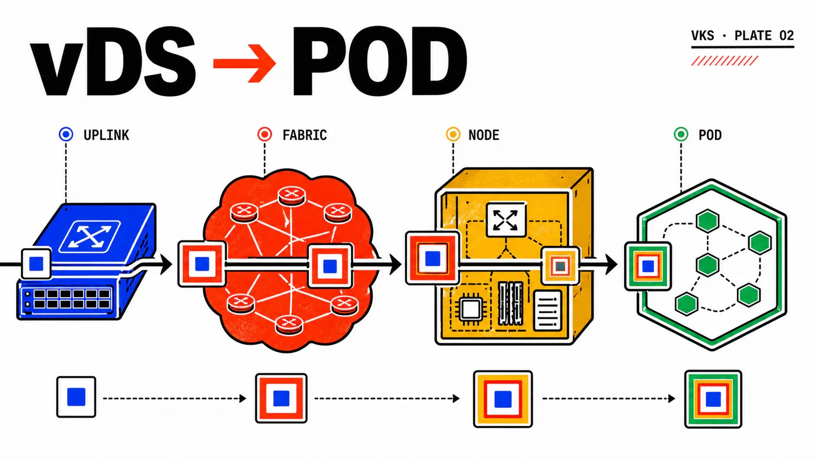
Before tracing a packet, you need to name the layers. Four components share the work.
vSphere Distributed Switch (vDS) — the L2 switch distributed across all ESXi hosts in the vSphere cluster. It carries Supervisor VM traffic, VKS node traffic, and management. It’s the foundation, but it doesn’t do much beyond L2 forwarding.
NSX (segments + routers) — the overlay layer. NSX segments are “virtual VLANs” carried by Geneve. Tier-0 and Tier-1 routers handle routing and NAT.
Antrea (VKS CNI) — the CNI inside the Kubernetes cluster. Antrea encapsulates pod-to-pod traffic and applies NetworkPolicies. It’s a second overlay, inside the node.
NSX Advanced Load Balancer (Avi) — the data plane that materializes Kubernetes Services of type LoadBalancer. It consumes an IP pool and exposes VIPs reachable from outside the cluster.
The conceptual trap. Many VKS newcomers think “Kubernetes networking” on one side and “vSphere networking” on the other. The reality is that a packet traverses both worlds sequentially, and every transition is a place where things can break. Understanding the transitions matters more than memorizing the config of each component in isolation.
The downstream path: user → pod
Let’s follow an inbound HTTP packet from the internet down to an application pod. Seven steps, each in a different layer.
[Client]
   ↓ public TCP/IP
[Edge firewall / inbound SNAT]
   ↓
[NSX Tier-0]              ← north-south boundary, BGP with the corp network
   ↓
[NSX Tier-1]              ← tenant gateway, dedicated to the VKS namespace
   ↓
[Overlay segment]         ← Geneve, carried by the vDS
   ↓
[VKS node (eth0)]         ← VM with worker pool IP
   ↓ Antrea (internal Geneve)
[Pod (vethXXX)]           ← container network
Step 1 — Edge. The packet hits the external edge (often a perimeter firewall), which forwards to the VIP exposed by NSX ALB. The VIP belongs to an Avi Service Engine, itself connected to an NSX segment dedicated to the Avi data plane.
Step 2 — NSX ALB. The Service Engine receives the packet, applies its L4/L7 logic (round-robin, cookie persistence, optional TLS termination), and picks a pod endpoint. The SE sends the packet to the pod’s IP — not to the node, to the pod directly, because pods are routable from NSX in the standard VKS topology.
Step 3 — Tier-0. If the Avi SE is in a different VRF from the namespace’s Tier-1, the packet goes up to T0 then back down. Otherwise T0 is bypassed. T0 is also the BGP advertisement point for pod CIDR routes — that’s how the corporate network learns about pod subnets.
Step 4 — Tier-1. The T1 router dedicated to the VKS namespace receives the packet and routes it to the overlay segment of the target worker node. The T1 carries the microsegmentation rules (Distributed Firewall) applied to that tenant.
Step 5 — Overlay segment. The NSX segment encapsulates the packet in Geneve and carries it through the vDS to the ESXi host running the target node. The VTEP-to-VTEP tunnel is transparent from the client packet’s point of view.
Step 6 — VKS node. The packet arrives on the node VM’s eth0. At this point it’s a plain packet with the pod IP as destination.
Step 7 — Antrea. Antrea receives the packet, routes it to the right network namespace via OVS, and delivers it on the pod’s veth. If the target pod is on another node, Antrea encapsulates again in internal Geneve — creating a double encapsulation (NSX Geneve + Antrea Geneve) with MTU implications you must know.
Double encapsulation and MTU
NSX Geneve adds ~52 bytes of header. Antrea Geneve adds the same. With a 1500-byte end-to-end MTU, the usable payload drops to ~1396 bytes. The recommended practice from Broadcom and VMware is an MTU of 1700 minimum on the vDS and physical underlay to absorb both encapsulations without fragmentation. Skipping this guarantees TCP MSS and PMTUD problems — among the most painful intermittent issues to diagnose.
The return path: pod → outside
A pod calling an external service (third-party API, database, registry) follows the reverse path, but with one important nuance: NAT.
By default, traffic leaving a pod is SNAT’d by the namespace’s Tier-1 to use the T1’s IP (or a public IP if Tier-0 is configured to do SNAT). The pod’s real IP isn’t exposed to the outside world.
Why it matters. In some contexts (egress firewalling, source-IP traceability, connections to on-premise databases), you may need to disable that SNAT and route the pod CIDR directly. NSX VPC (introduced in VCF 9) makes this configuration simpler than hand-crafting static routes.
The trap. If you disable SNAT for a namespace but your corporate network doesn’t learn the pod CIDR via BGP, return packets will never come back. This is the classic asymmetric routing scenario that creates partially functional connections (SYN goes through, SYN-ACK doesn’t return) and intermittent errors.
T0 vs T1: where to draw the boundary
A design decision that always comes up: how many Tier-0s, how many Tier-1s, who shares what.
Model — one T0, multiple T1s, one T1 per namespace or per team group.
Strengths — simple to operate, centralized BGP, fewer NSX Edge resources. The default pattern for most organizations.
Limits — no strong network isolation between tenants at the north-south level. For tenants with distinct regulatory constraints, it’s not enough.
Model — one T0 per tenant or per environment (prod/non-prod), with dedicated Edges.
Strengths — strong isolation, independent BGP sessions, contained blast radius. Recommended for financial services or healthcare.
Limits — Edge resource cost (each active/active T0 consumes two Edge VMs), operational complexity. Justify with a real isolation need, not convenience.
Model — NSX VPC, the abstraction introduced in VCF 9 that bundles T1 + segments + policies under a “VPC” entity aligned with the AWS/Azure VPC concept.
Strengths — declarative model, self-service via API, alignment with public cloud patterns. Drastically reduces ticket volume to the NSX team.
Limits — young feature, learning curve for teams used to the classic T0/T1 model. Migrating from a traditional model isn’t trivial.
Stated recommendation. For a new VCF 9 platform, start in NSX VPC. For an existing platform on classic T0/T1, don’t migrate for the sake of migrating — the value of the VPC model emerges when tenant count goes past 10 or application teams start asking for network self-service.
NSX ALB and LoadBalancer Services
The integration between VKS and NSX ALB is what makes the developer experience acceptable. You need to understand how it works to size it correctly.
The AKO controller (Avi Kubernetes Operator) runs inside the VKS cluster and watches Kubernetes Services. When a LoadBalancer Service is created, AKO calls the Avi controller API to provision a VirtualService and allocate an IP from the pool configured at the vSphere namespace level.
Service Engines are Avi VMs deployed in a dedicated NSX segment. They host the VIPs, run the L4/L7 logic, and forward traffic to pod endpoints. A SE can host hundreds of VirtualServices depending on its sizing — but concentration creates blast radius.
The IP pool is a finite resource. Each LoadBalancer Service consumes one IP. On a cluster with many exposed microservices, the pool can run out faster than you’d think. Monitor consumption early and adjust before the application team starts seeing provisioning errors.
Ingress = a shared VIP
Rather than exposing every service with a dedicated LoadBalancer Service, deploy an Ingress controller (Contour, NGINX) that consumes a single VIP and routes at L7 to internal services. This cuts IP pool consumption by orders of magnitude and gives you a single point for TLS termination and HTTP observability.
Overlay vs VLAN-backed segments
When you create an NSX segment, you choose between overlay (Geneve) and VLAN-backed.
Overlay. The standard mode for VKS workloads. Overlay segments are independent of the datacenter VLAN addressing plan, allow L2 mobility between distant ESXi hosts, and benefit from distributed microsegmentation. Cost: the double Geneve encapsulation already mentioned.
VLAN-backed. Useful for specific cases: legacy workloads that must be exposed directly on a datacenter VLAN, regulatory constraints that forbid overlay, integration with external equipment that speaks native VLAN tagging. Avoid by default for VKS workloads — microsegmentation is coarser and mobility is limited.
Gotchas and limits
Mis-sized MTU = intermittent failures
Asymmetric routing with SNAT disabled
Distributed Firewall = golden rules to know
NSX ALB pool exhaustion
Service Engine sizing: prod ≠ POC
VRF leaks and tenant cross-talk
Conclusion and what’s next
Key takeaways. VCF 9 networking layers four planes: vDS, NSX, Antrea, NSX ALB. A packet traverses each in sequence, and every transition is a diagnostic point. MTU is the first thing to check on any intermittent issue. The T0/T1/VPC choice commits you for years — start in VPC for new platforms. NSX ALB transforms developer experience but must be sized explicitly.
What’s next. The next article covers day-2 operations on VKS: cluster lifecycle via CAPI, upgrades, and the observability stack. Once networking is understood, that’s the other big chantier of going to production.
Resources.
Going further:
- Broadcom TechDocs — NSX Concepts — reference on T0/T1, segments, DFW
- Broadcom TechDocs — VKS Networking — VKS + NSX integration
- NSX VPC Design Guide — multi-tenancy patterns
- Avi Kubernetes Operator (AKO) — official controller documentation
- Antrea Documentation — Antrea CNI reference
Get the next one by email
New articles and series, sent when they are published. No other mail.